
OVERSUSPENSION
scientific test
Scientific verification test of the Oversuspension device on 12/21/2022 in:
Orioli
Suspension & Racing
Majano-Italy
The objective of the test was to verify the operation of the Oversuspension resonator and check the amount of energy it is capable of accumulating and returning in opposite phase.
To carry out this test, we used:
A suspension test bench manufactured by LABA7 (the same one used by KTM and WP)
A laboratory oscilloscope, a Helatech Easy logger data acquisition system
A Milwaukee model M12 TD thermal imaging camera equipped with a laser pointer
A Mitutoyo comparator to measure load cell deformation
Two accelerometers.
Two different shock absorbers were then tested:
An Ohlins TTX road shock absorber in SBK version (reviewed by the Andreani Group)
A WP Link off-road shock absorber (reviewed by Orioli sospensioni).
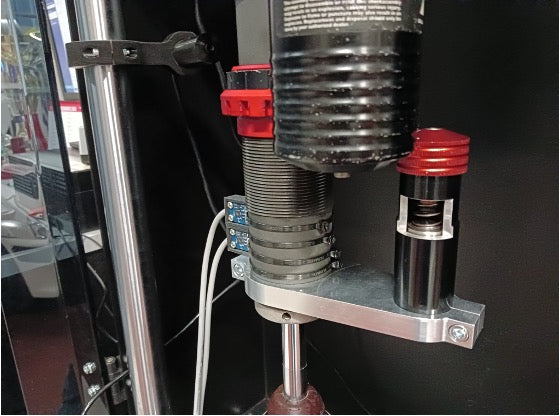
The test was carried out as follows:
Both shocks were connected to the dyno with the appropriate brackets and then the resonator was connected to the shock body via the 2017 retensioned alloy bracket.
The theory consisted of measuring with the few tenths of displacement of the shock absorber body due to the deformation of the load cell how much energy the device could accumulate and, through the push-pull reaction, returning this energy to the system by measuring the difference in the load cell.
At the same time, two accelerometers were attached to the shock absorber body: the first was connected to the oscilloscope, the second to the data acquisition system set with a sampling rate of 100 HZ, and finally, the tests were monitored with a thermal camera. to evaluate the work expressed in heat of the device.
The tests were repeated 10 times with and without the device, and the compared results revealed deviations of around 2 to 3%, therefore completely irrelevant, while the trends of the curves were almost identical, so the test performed can define yourself as a scientist.
The measurements carried out were the following:
The shock absorbers were tested at different speeds with and without the device, the first speed was 100mm/s, the second 200mm/s, the third 400mm/s, the fourth 600mm/s. The deformation of the load cell during the first test was 0.3 mm (at a speed of 100 mm/s), the second deformation measurement was 0.4 mm (at a speed of 200 mm/s) , the third strain measurement was 0.5 mm (at a speed of 400 mm/s), the fourth strain measurement was 0.6 mm (at a speed of 600 mm/s).
All measurements were made with the shock body at a temperature of 60 degrees.
The tI test revealed the energy storage capacity of the resonant system from low speeds, i.e. 100mm/s, and established that at a speed of 600mm/s the energy returned by mathematical difference in the load cell is 55N equal to 5,608 kg.
It was also observed that as the speed of the shock absorber increases, the amount of stored energy increases linearly, the shock absorbers were used with strokes from 20mm to 40mm.
It could be observed that the increase in the shock absorber stroke by moving the connecting rod assembly in the main thrust engine on the test bench corresponded to an increase in the work of the device and a change in the signal amplitude, a result that confirms the correct counterphase displacement of the device in relation to the shock absorber body.
The oscilloscope precisely verified the different behavior of the shock absorber body by reducing the amplitude of its oscillation. The data logger calibrated with a sampling frequency of 100HZ allowed the two out-of-phase signals to be compared, confirming the out-of-phase effect with an accuracy of 98%.
Finally, the thermographic image allowed us to see the work done by both the shock absorber and the device.
The test thus demonstrated the resonator's ability to resonate with the system and accurately shift out of phase, reducing the load on the test bench's readout cell. Simultaneous and repeated measurements confirmed with scientific precision the work done by the device.
Final considerations:
The Oversuspension device therefore demonstrated an absolute degree of effectiveness in counteracting the elastic energy released by the tire, and a natural predisposition to naturally position itself in precise counterphase counteracting all the forces released by the decompression of the tire.
This confirms the sensations that thousands of users around the world have had of the device from which an overall increase in the effectiveness of the rear suspension unit is derived.
It must also be taken into account that these results have been obtained taking advantage of the minimum movement given by the load deformation of the cell and, therefore, less than one millimeter.
In the position in which it normally works, that is, at the end of the suspension assembly, where the movement is even greater, the effectiveness increases exponentially.
The increase in the tire's average ground pressure therefore translates into a series of dynamic advantages, greater traction during acceleration, greater braking control and effectiveness especially during ABS intervention, greater phase coherence between the suspension and the release elasticity of the tire, a strong reduction in aquaplaning due to the lower incidence of water in front of the tire, and a reduction in mechanical fatigue throughout the vehicle.
physics experiment
Imagine that the oscillating movement is the rebound of your motorcycle tire, and that the suspended golden mass represents the work of Oversuspension, keeping your wheel glued to the ground.
anti-seismic technology
skyscraper collapse
Starting from the same principles of Physics, a suspended mass is installed at the tops of skyscrapers to counteract in the opposite direction the energy generated by earthquakes and storms.